Technical drawings
Technical drawings and two-dimensional design boards of parts and assemblies
Technical drawings of parts and assemblies
Our design office produces technical drawings of parts and assemblies, for the production and assembly of machines and plants.
Technical drawing and mechanical technical drawing, whose output takes the form of two-dimensional design boards, can be carried out after the design phase, but when required by the customer, can also be carried out as a single activity, on the basis of existing designs.
Design board creation is an extremely important step and plays a key role in the production and assembly of the machine, because the design board shows all the characteristics and other important information about the plant or machine. Furthermore, we always channel special attention and professional technical skills into the production of 2D design boards for production purposes, with all the necessary characteristics and other information.
Having first established the work method with the customer, we start work on producing the technical drawing. Customers sometimes send us examples of technical drawings done in the past, which we can use as a basis for creating the new ones.
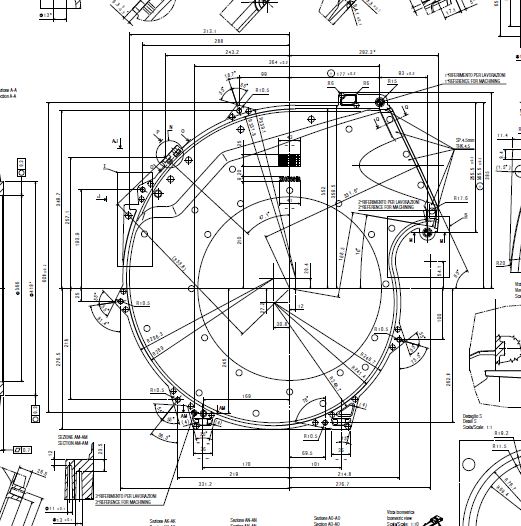
Dimensioning of technical drawings
A technical drawing is a graphical representation of one or more geometrical elements, according to which a spatial meaning is associated with each sign.
The dimensioning of the technical drawing is the most important step in the realization of a project, as it shows the important linear and angular dimensions for the purposes of the drawing itself, such as the length, width and height of the object to be made.
The technical drawing enables the machine tool operator to make the component on the basis of the notes/indications provided by the technical designer of the part.
The correct tolerance is inserted on the basis of the material of which the component in question is made. Chain dimensioning and parallel dimensioning can also be inserted:
- Chain dimensioning is used when you want to show multiple measurements next to each other
- Parallel dimensioning is much less widely used and is specific to certain types of customer only; all the necessary measurements are shown, starting from an origin.
After discussions with the customer, we recommend the most suitable type of dimensioning for their needs, based on the information we receive.
Professional profiles involved
Under the coordination of a Project Team Manager, our technical drafters, designers and technical writers produce complete, precise technical drawings.
Mechanical CAD Drafter
Mechanical designer
Team manager
Technical writer
Software used for technical drawings
La conoscenza approfondita dei principali software di disegno tecnico ci permette di soddisfare
Our in-depth knowledge of the main technical drawing software applications enables us to meet our customers’ requirements at all times.
sempre le esigenze dei nostri clienti.

Autodesk Autocad Mechanical
AutoCad con applicativo TOP

ME10

Think3 DM.9.0 GBG

Catia

Solidworks
Inventor

Pro Engineer – CREO 2-3
One space Co-create
Technical Drawings: Case Studies and Successfully Completed Projects
Cheese lifter
Studio A.S.E. worked on the project of a seasoned cheese lifter, for the extraction out of the seasoning tank.
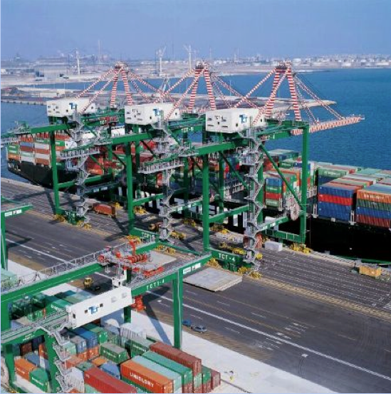
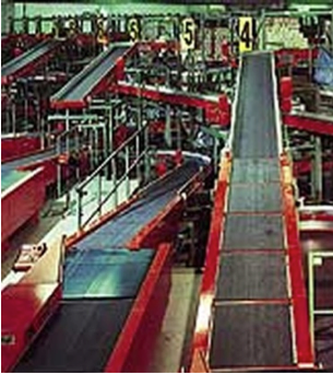
Design of staircases, gangways and high-level walkways for port cranes
Studio A.S.E. worked on the designing of stairs and galleries installed on harbour cranes, which allowed the personnel to reach the areas of the crane and manoeuvring or repairing the machine when necessary.